GoPro Hero3 Black Field of View
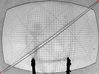
I got two GoPro Hero3 Black cameras and am planning a panoramic project with them. However, to do the project correctly and accurately, I need a good read on their field-of-view. So, I set up a tripod and a grid and a tape measure, and took a few photos. Here they are, desaturated and contrast-enhanced, with central red dots and some annotations. First, measuring the diagonal FOV:
Next, the horizontal FOV:

Finally, the vertical FOV:

The front of the camera lens was almost exactly 17 inches from the grid. The camera body started about 17.25 inches from the grid. Assuming the sensor is embedded some distance into the body, I used an estimated field-to-sensor distance of 17.5 inches. This yields the following field-of-view, in degrees:
Diagonal: 146
Horizontal: 121
Vertical: 93
Doing a little interval math on the field-to-sensor distance shows these angles are accurate to about plus or minus 1.5 degrees.
Interestingly, Photoshop seems unable to correct the barrel distortion of the GoPro's built-in lens. The EXIF information says it is a 2.77mm f/2.8. I suspect it is some sort of a non-linear distortion (i.e. stronger toward the corners than in the middle). I'll do a little math and see what I can figure out...
Edit - Dec 29 2012
I wrote a program to account for the spherical projection the lens uses. It is a very straightforward projection, and works out to a horizontal field-of-view of roughly 114 degrees (i.e. a little smaller than I calculated, probably due to the difficulty of reading the tape measure numbers as they get squished toward the edge). Basically, you can reproject the pixels to a flat plane by scaling the distance of each pixel from the center of the image proportional to the atan of that distance, divided by the constant which comes out to half the horizontal field-of-view:
Using this correction, here is the diagonal FOV image, reprojected:
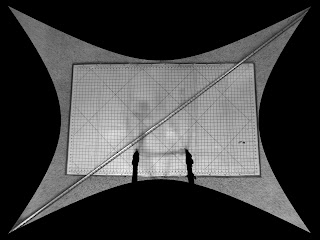
The keystoning of the sewing board is due to the fact that the camera was not facing directly perpendicular to it, so there is a perspective distortion. Two things show that this is the correct projection:
1. The left and right edges of the sewing board, reasonably straight in reality, are straight in this image
2. The tape measure is a consistent width across the entire image.
Edit 2 - Mar 28, 2013
To make it absolutely clear how I did this, here is a code fragment from the C program I hacked together for this. Strictly point-sampled (no interpolation) but good enough to demonstrate the math.
/* Half of the horizontal field-of-view, in degrees */
#define WIDTH_HALF_ANGLE 57
int i, j; // loop counters
int w, h, c; // input: image width & height & # of components (typically 3 or 4)
int nw, nh; // Expanded width-height range to pick up all the pixels
double x, y, r, ang; // temporary floating point variables
int ix, iy; // calculated indices
unsigned char *img, *dst; // Source and destination raster images
nw = w * 2.5;
nh = h * 2.5;
for (i = 0; i < nh; i++) {
for (j = 0; j < nw; j++) {
// Calculate fractional x/y coords - (0,0) is the center of the image
x = (j - nw*0.5) / (0.5 * w);
y = (nh*0.5 - i) / (0.5 * w);
// Calculate distance from center, and normalize to a unit vector
r = sqrt(x*x + y*y);
if (r > 0.0) { x /= r; y /= r; }
// Calculate the angle of this unit vector from
// horizontal-to-the-right
ang = atan(r) * 180 / (WIDTH_HALF_ANGLE*M_PI);
// Calculate adjusted distance this pixel really was
r = ang * w/2;
// Figure out where in the image that distance is
// (nearest neighbor sampling)
ix = x*r + w/2 + 0.5;
iy = h/2 - y*r + 0.5;
// If that source pixel is within the image bounds...
if ((ix >= 0) && (iy >= 0) && (ix < w) && (iy < h)) {
// ... then copy it over
for (n = 0; n < c; n++) {
dst[c*(i*nw + j) + n] = img[c*(iy*w + ix) + n];
}
}
}
}

Next, the horizontal FOV:

Finally, the vertical FOV:

The front of the camera lens was almost exactly 17 inches from the grid. The camera body started about 17.25 inches from the grid. Assuming the sensor is embedded some distance into the body, I used an estimated field-to-sensor distance of 17.5 inches. This yields the following field-of-view, in degrees:
Diagonal: 146
Horizontal: 121
Vertical: 93
Doing a little interval math on the field-to-sensor distance shows these angles are accurate to about plus or minus 1.5 degrees.
Interestingly, Photoshop seems unable to correct the barrel distortion of the GoPro's built-in lens. The EXIF information says it is a 2.77mm f/2.8. I suspect it is some sort of a non-linear distortion (i.e. stronger toward the corners than in the middle). I'll do a little math and see what I can figure out...
Edit - Dec 29 2012
I wrote a program to account for the spherical projection the lens uses. It is a very straightforward projection, and works out to a horizontal field-of-view of roughly 114 degrees (i.e. a little smaller than I calculated, probably due to the difficulty of reading the tape measure numbers as they get squished toward the edge). Basically, you can reproject the pixels to a flat plane by scaling the distance of each pixel from the center of the image proportional to the atan of that distance, divided by the constant which comes out to half the horizontal field-of-view:
r = atan(r) * (180 / (WIDTH_HALF_ANGLE*M_PI)) * (w/2);
Using this correction, here is the diagonal FOV image, reprojected:

The keystoning of the sewing board is due to the fact that the camera was not facing directly perpendicular to it, so there is a perspective distortion. Two things show that this is the correct projection:
1. The left and right edges of the sewing board, reasonably straight in reality, are straight in this image
2. The tape measure is a consistent width across the entire image.
Edit 2 - Mar 28, 2013
To make it absolutely clear how I did this, here is a code fragment from the C program I hacked together for this. Strictly point-sampled (no interpolation) but good enough to demonstrate the math.
/* Half of the horizontal field-of-view, in degrees */
#define WIDTH_HALF_ANGLE 57
int i, j; // loop counters
int w, h, c; // input: image width & height & # of components (typically 3 or 4)
int nw, nh; // Expanded width-height range to pick up all the pixels
double x, y, r, ang; // temporary floating point variables
int ix, iy; // calculated indices
unsigned char *img, *dst; // Source and destination raster images
nw = w * 2.5;
nh = h * 2.5;
for (i = 0; i < nh; i++) {
for (j = 0; j < nw; j++) {
// Calculate fractional x/y coords - (0,0) is the center of the image
x = (j - nw*0.5) / (0.5 * w);
y = (nh*0.5 - i) / (0.5 * w);
// Calculate distance from center, and normalize to a unit vector
r = sqrt(x*x + y*y);
if (r > 0.0) { x /= r; y /= r; }
// Calculate the angle of this unit vector from
// horizontal-to-the-right
ang = atan(r) * 180 / (WIDTH_HALF_ANGLE*M_PI);
// Calculate adjusted distance this pixel really was
r = ang * w/2;
// Figure out where in the image that distance is
// (nearest neighbor sampling)
ix = x*r + w/2 + 0.5;
iy = h/2 - y*r + 0.5;
// If that source pixel is within the image bounds...
if ((ix >= 0) && (iy >= 0) && (ix < w) && (iy < h)) {
// ... then copy it over
for (n = 0; n < c; n++) {
dst[c*(i*nw + j) + n] = img[c*(iy*w + ix) + n];
}
}
}
}


Comments
Just a little confused on the expression you have provided to perform this op. If you would be kind enough to help me understand, I would greatly appreciate it!
r = ?
Width_Half_Angle = ?
M_PI = ?
w = ?
To answer the second question - yes, this is the "photo" GoPro setting. I don't know whether the FOV is the same between Hero2 and Hero3, sorry.
I would be very grateful if you could confirm or refute that this is the case: that videos record (or can record) at a substantially wider angle than you can take stills.
The GoPro site is suspiciously vague when it comes to the specifics of the image... maybe they think that someone is actually interested in the number of glass elements in their lens.